Release time:2025-05-22
A battery is a device used for energy conversion and storage. There are many types of lithium batteries, which are mass-produced and used in today's society. Lithium batteries have created a lot of convenience for humans, and many places require lithium batteries. In a steel shell lithium battery, the outer shell is made of steel shell, the positive electrode plate is made of aluminum foil, the negative electrode is made of copper foil, the positive electrode material is lithium cobalt oxide, the negative electrode material is graphite, the separator is a polymer film, and the electrolyte is ethylene carbonate, in which lithium hexafluorophosphate is dissolved.

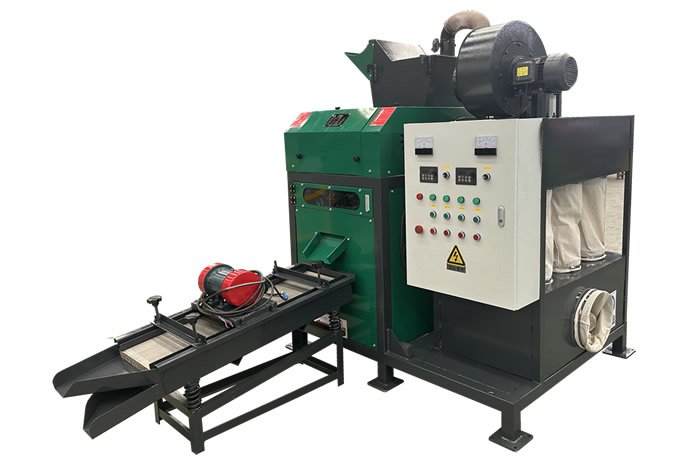
From the perspective of environmental protection and sustainable development, when lithium batteries cannot be used, they need to be recycled to reduce environmental pollution. Lithium battery processing and recycling equipment and crushing devices can effectively crush waste lithium batteries. The mixed granular materials, such as lithium cobalt oxide powder and graphite powder, can be filtered out from the bottom outlet, and the bulk lithium battery materials flow to the sorting device. The steel shell can be adsorbed on the conveyor belt, and the status is sent to the material pool, greatly improving work efficiency, saving costs, and high utilization rate. Waste lithium batteries are crushed, classified, and recycled in an environmentally friendly and reasonable manner.
Lithium battery recycling and processing equipment, including a crushing box, with a feeding hopper fixedly installed at the top of the crushing box, support legs fixedly installed at the bottom of the crushing box, a discharge pipe fixedly installed at the bottom of the crushing box, a conveying channel fixedly installed on the right side, and two conveying rollers fixedly installed inside the conveying channel. The middle diameter of the conveying roller is larger than the diameter of its two ends, and a conveyor belt is set between the two conveying rollers. On the surface of the conveyor belt, there are evenly distributed leakage holes. The conveyor roller on the right extends out of the conveyor channel, and a collection box connected to it is fixedly installed at the bottom of the conveyor channel.
A drive motor is fixedly installed on the left and right sides of the crushing box and the lower left corner of the front part of the conveying channel. The output shaft of the drive motor on the crushing box is fixedly installed with a crushing shaft, and the crushing box is rotatably connected to the crushing shaft. On the inner wall of the other side, two crushing shafts are placed parallel to each other in the vertical direction. The top crushing shaft is fixed with inclined blades at the bottom and top, and auxiliary blades are fixed on both sides of the inclined blades. The bottom and top of the bottom crushing shaft are both fixed with vertical crushing blades. The driving motor on the conveying channel is fixedly connected to the core shaft of the track roller.
Inside the crushing box, located below the vertical crushing blades, a downward sloping filter layer is installed around the perimeter, and a discharge hopper is fixedly installed on the right side of the crushing box. The mesh layer is connected, and the right side of the discharge hopper extends above the surface of the conveyor belt. The top of the material conveying channel is fixedly installed with an air intake fan, and one side of the air intake fan is fixedly installed with an air main pipe. The air main pipe is fixedly installed at the top of the material conveying channel, and the bottom of the air main pipe is fixedly installed with an air supply branch pipe. The bottom of the air supply branch pipe is fixedly installed with an air supply nozzle, which tilts forward, and the rear air supply nozzle tilts backward. A support frame is fixedly installed at the bottom of the collection box, and a support plate is set inside. An isolation net layer is fixedly installed between the inner walls on both sides, and the middle of the isolation net layer is located above the support plate. A sealing door is set on one side of the collection box. A collection fan is fixedly installed inside the collection box, and a U-shaped inlet duct is fixedly installed on one side of the collection fan, with the inlet duct facing downwards. A gas delivery pipe is fixedly installed on one side of the collection fan, which runs through the lower part of the isolation mesh layer.
Compared with existing technology, the beneficial effect of the production line of the utility model is that the diameter of the middle part of the conveyor roller is larger than the diameter of its two ends, which can make the middle part of the conveyor belt surface higher and be transported to the main and branch pipes through the inlet fan. Gas is sprayed from the gas nozzle to achieve the effect of cleaning impurities on the raw material. Then, the dust in the conveying channel is transported to the bottom of the isolation mesh layer through a U-shaped inlet duct and an air duct by a collection fan, achieving the effect of filtering impurities. It can clean the impurities adhered to the raw material and reduce the impurities in the recovered raw material.
If you have any requests or suggestions, please contact us! WhatsApp:+8613298332678,+8613253662638


TEL
+86 13298332678
Work time
from Monday to Friday
After sales service
+86 13253662638
